Roadbuilder
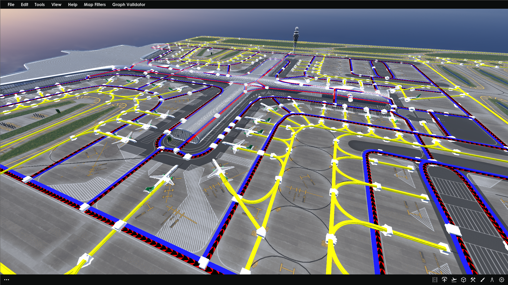
A tool to develop one-to-one scale maps of airport infrastructures and road networks to enable accurate airport modeling and simulations.
This is a brief overview of Aurrigo's Roadbuilder tool and its user interface, which I designed and developed using the Godot game engine. Unfortunately due to the nature of the software, I’m unable to delve into the specifics of all the features encompassing Roadbuilder or the design processes involved in creating the user interface and interactions. If you'd like to learn more about this project, please don't hesitate to reach out to me at harveyibeynon@gmail.com.
What is Roadbuilder?
Roadbuilder is one of the three core software tools that make up Aurrigo’s Auto-Sim product, a comprehensive simulation software designed to model the daily operations of an airport. The three software tools that make up Auto-Sim are as follows:
Roabuilder: Enables the creation of a one-to-one scale map of an airport, including accurate road networks, infrastructure placement, and important locations.
Sim Manager: Allows users to set crucial simulation parameters, such as flight schedules, personnel numbers, vehicle fleets, and baggage details.
Visualiser: A data dashboard and playback tool where users can view and analyse the simulation results.
This case study will focus on the first component, Roadbuilder. It allows users to create precise, scaled maps of airports, facilitating more accurate simulations of ground operations and vehicle movements. These simulations provide valuable insights, such as stand-to-lateral baggage timings and charging times and battery levels for electric vehicles.
All the UI components within this tool are built from the Aurrigo Design System. This ensures that the style and components within this tool are unified with the rest of the Auto-Sim suite as well as maintains the same branding styles as the rest of Aurrigo’s products and marketing materials.
Main Menu
All map creation tools are accessible via the main menu, located in the bottom right-hand corner of the screen. These tools are represented by icons and are organised into the following categories:
Road placement: Enables users to place and connect road networks.
Container placement: Allows users to position key locations, such as stands, laterals, charging stations, and other critical areas.
Runway placement: Facilitates the placement of runways for aircraft takeoff and landing.
Props placement: Lets users add various assets to the map to enhance visual detail and improve visualisation.
Infrastructure: Provides tools for placing electrical networks and traffic signals.
Location paint tool: Allows users to zone specific areas of the map that share common resources and locations, such as different terminals.
Planning tool: Includes features for saving notes, using a ruler to measure distances, and ensuring more accurate map representation.
Settings tool: Offers options to adjust the camera view, road widths, and auto-save preferences.
Road Placement Tool
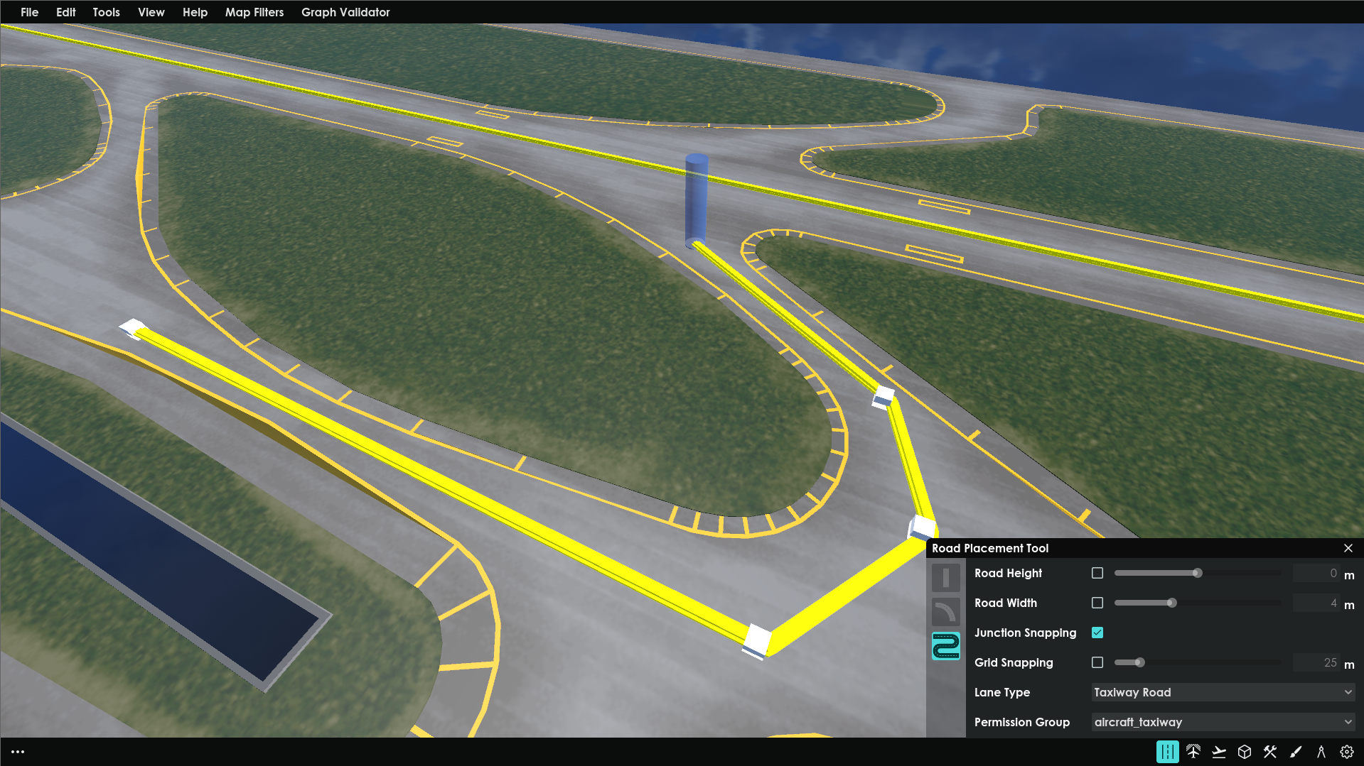
The Road Placement Tool allows users to create various types of roads, including straight, curved, and free-form. Users can adjust the road’s height and width using horizontal sliders and enable snapping for precise alignment. The tool also includes options to select the road type—such as single-lane, two-way roads for ground vehicles, or taxiways for aircraft. Additionally, users can assign permission groups to control which vehicles are allowed to travel on specific roads.
The UI for all placement tools is designed to be unobtrusive, ensuring users have maximum space to place roads, containers, and other elements on the map. This minimalist approach allows for a more seamless and focused mapping experience.
Users add roads to the map by placing road nodes at desired connection points. These road nodes attach to the ground plain and automatically snap to other road nodes, seamlessly connecting roads into a unified network.
Users can edit roads after placement, including the ability to curve sections for more realistic and dynamic road layouts. This flexibility allows for more accurate representations of real-world road networks within the map.
Container Placement Tool
For the simulation to understand where locations important to an airport’s operations are, users add containers to the map. A container represents any location used for a vehicle's mission in the simulation, these containers represent stands on the airport runways, charging stations or baggage laterals.
Above is an example of a stand being placed by the user. The container type is selected as a stand, and the user adds a stand item to the container also with parking locations for the vehicles that would be servicing that flight.
The buttons on the slide are listed as follows:
Add Root Node: This is the initial node that creates a container. These nodes need to be connected to the road network to allow vehicles to travel to and from the container. Container nodes can be named by the user, for example, “Gate C12” as well as set the container type.
Parking Spaces: Multiple parking spaces can be placed in a container and specify where the vehicle will park when undergoing a mission within the container. The user can also specify which vehicles are allowed to park in the parking space. Parking spaces can also be connected to chargers if its a charging location.
Stand: Only one stand can be added to a container and specifies when the aircraft will park when being serviced.
Substations: Containers can also be used for infrastructural locations such as a substation. These allow the user to connect electrical networks together and specify the the total voltage each stage of the network has.
Chargers: These allow users to specify the charging capacity of a charger and which substation it is connected to to gather accurate charging metrics for the simulation.
Additional Nodes: These are additional nodes that act as other entrances and exits of the container for other vehicles. For example a stand may have a root node connected to the road network to allow vehicles to enter and park on the stand, and an additional node connected to the taxiway network to allow aircraft to navigate from the runway to the stand and vice versa.
Editing Roads
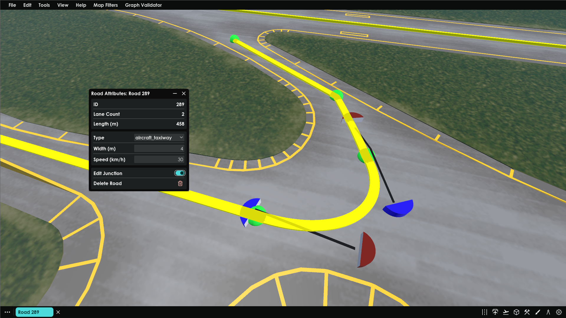
When the user clicks on a placed road the road attribute window appears. This window allows the user to check metrics on that road, edit any details attached to that road instance and edit the road junctions or delete the road all together.
Selecting the edit junction road switch changes the roads junction node colour and allows users to adjust the roads position or curve any parts of the road.
Editing Containers
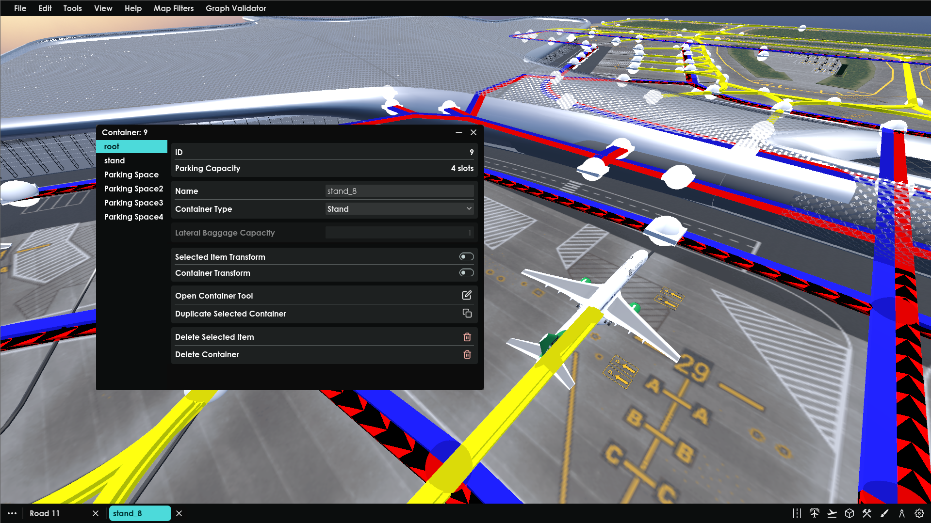
When the user clicks on a container or any of the items within the container, the container attributes window appears. This window has a vertical tab list of the items within the container, the tab currently active depends on the item of the container clicked. For example, if the user clicks on a specific parking space on a stand container, then that parking space item is set to the active tab.
The type of item selected on the tab determines the input field shown on the window. With the case above the root node is active so the window shows information assigned to that root node. ID is the unique number used within the simulation, the total number of parking spacing attached to that container, the container’s name and the container’s type.
Two switches allow the user to either change the position of the specific item selected or the position of the whole container. The user can also press the “Open container tool” button to be able to add new items to that container. The user can also duplicate the whole container and its items to be able to create new containers of the same type, For example duplicate a stand and all the parking spaces within it for different gates. There are also two delete buttons to delete the selected item or the whole container.
Open and Close Tab System
Feedback provided from the simulation engineers was that it was annoying to have to open, close and reopen the attributes windows for multiple roads and containers when working with more than one. To improve the productivity of creating and editing maps a tab system was designed and developed.
The solution was to allow users to minimise attribute windows into a horizontal tab list, where they can open, minimise and close other attribute windows. When the user opens an attribute window for the first time a tab is created. Tabs that are open are highlighted, currently only one tab can be open at a time, although further feedback has provided that the additional feature of being able to “split” a tab or have more than one open may be required down the line.
The button with the three-dot icon opens a pop-up that shows a list of all the tabs, here users are able to open and close specific tabs and search for a tab. By clicking the icon button next to the search bar users are also able to close all tabs, or close just the road tabs or just the container tabs.
Configuration Menu
From the top main user are able to access the configuration menu. This menu allows user to configure settings across the whole map. Each page is accessible from the vertical tab list. The image below show the “All Roads” page open which lists all the roads on the map. This page allows users to see and edit all the roads placed on the map. Users can search for a specific road, change a roads vehicle permissions, max speed and width. The three buttons on the side move the camera to that road, open the road’s attribute window or delete that road. Users are able to click on the table headers to apply filters or sort the items in the shown
For example the user is looking at all the roads filtered by TaxiWays and sorted by length for largest to smallest. When filters are applied to a head they are highlighted and it chevron icon changes to a filter icon or sort icon depending on what is selected.
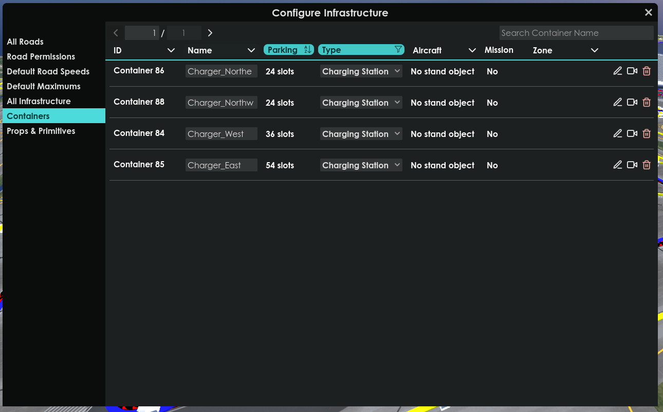
Containers can also be filtered on the container page. For example, the user can filter the containers by the type of charging station and is sorting by parking spaces from lowest to highest.
Graph validator
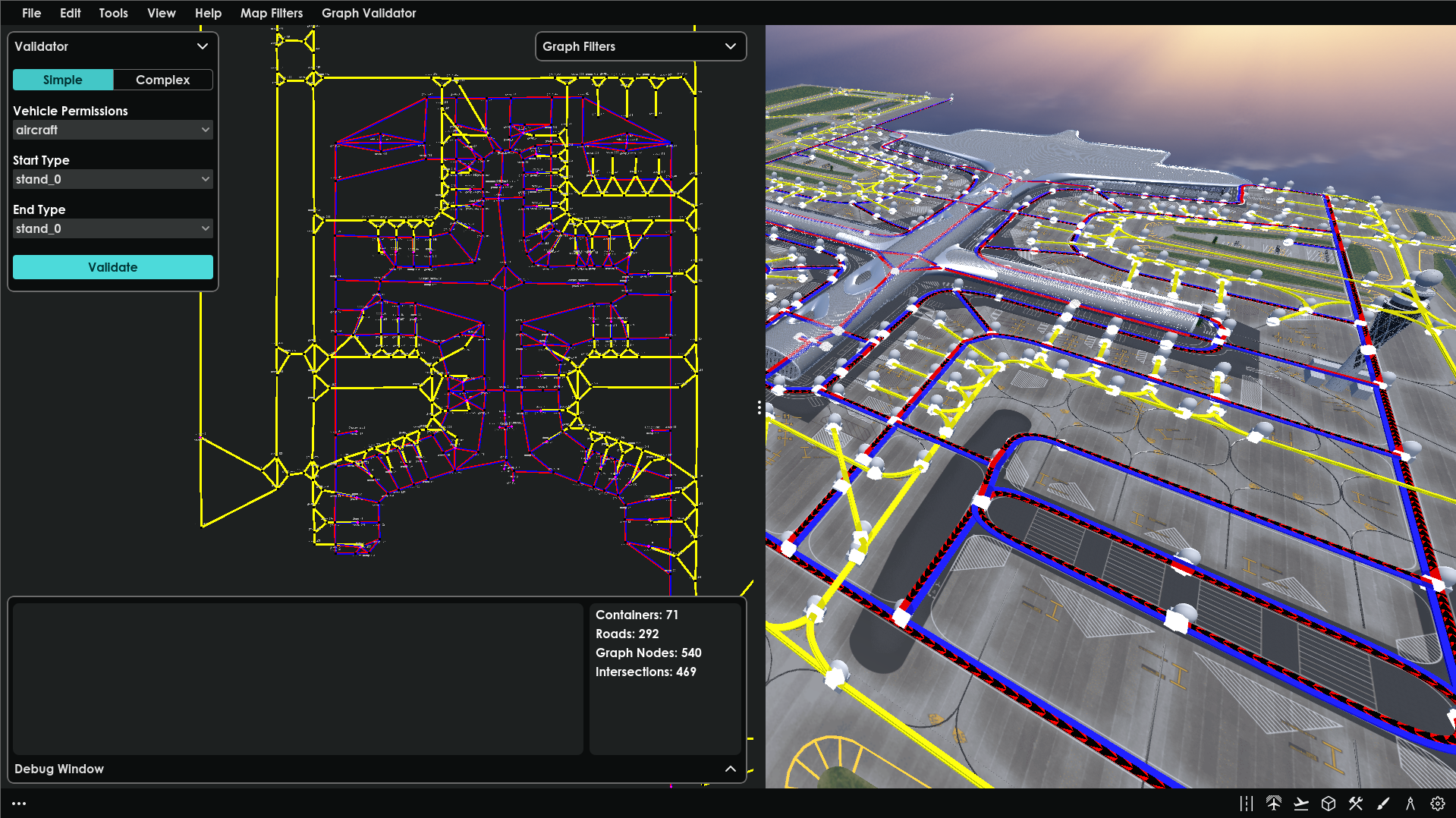
Feedback has shown that once a user has added all the roads and containers that make up an airport, they require a tool that tests whether or not the road network is valid or not. The graph validator tool allows users to see the graph of the road network and test different journeys across the maps. The graph validator shows a 2D map of the road network, users are able to filter what is shown on the graph depending on their preferences, for example if they want to see the cost of each road that the path finding tool used in the simulation used to navigate through the map via the sorted distance.
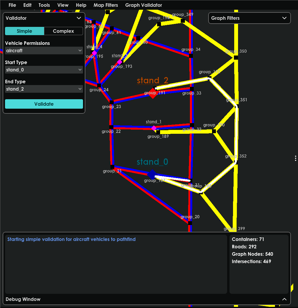
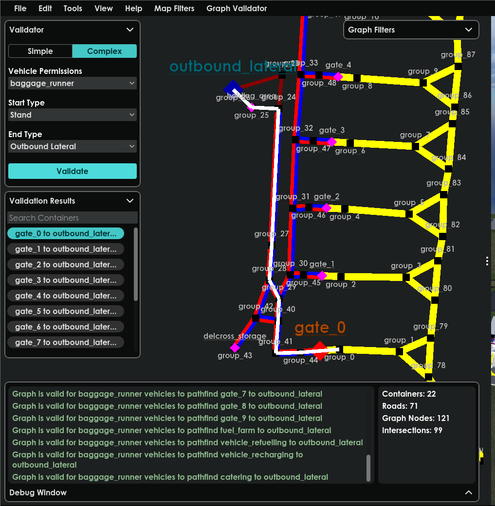
The user is able to do two types of validation checks. The first is called a simple validation, which allows the vehicle to choose a vehicle type, and validate if that vehicle can navigate from a chosen starting location to a chosen end location. The second validation type is the complex validation which is selected via the switch on the validator card. This validation allows the user to choose a vehicle, and a start type and end type. For example Baggage Tractor navigation form a stand to and inbound lateral. The validation will then run through all possible connections for all the stands to get to all the inbound lateral containers in the map. Resulting in a list of results for the user to click and examine the route taken.
The first example is a simple validation check to see if an aircraft can travel from stand 0 to stand 2. The white line indicated the path taken, with the blue square being the start location and the red square being the end location
The second example a complex validation to check if a baggage runner can navigate from all stands to all outbound laterals. The card labeled validation results shows a list of all the possible journeys. When the user selects one that path is then drawn on the 2D map.
All cards on the graph can be minimised to give the user more room to examine the graph and only open the cards that are needed.
